Network performance of SoC with TCP/IP Offload engine, W7500, for Internet of Things
We have measured TCP throughput of W7500 depending on RX buffer size, Main bus clock and DMA andused HW, SW and Toos as belows,
- Hardware: WIZwiki_W7500
- Software: TCP recv only (Firmware)
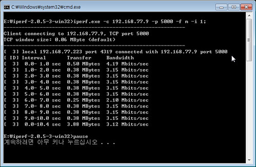
- Bandwidth Measurement Tool : Iperf
What is SoC with TCP/IP TOE, W7500
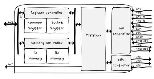
The 7500 chip is the one-chip solution which integrates an ARM Cortex-M0, 128KB Flash and hardwired TCP/IP TOE which is a market-proven hardwired TCP/IP stack with an integrated Ethernet. Using TOE allows users to implement the Ethernet application by adding the simple socket program. It’s faster and easier than using any other Embedded Ethernet solutions, especially internet of things. In addition, TOE can provide high and stable network performance on target system.
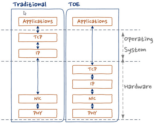
Traditional system could be used operation system for TCP/IP stack. It means more memory and calcurate resources in IoT system which is limited resources extremely. TOE allows to offload the processing of TCP/IP protocols from the host microcontroller,
In TCP/IP protocol stack of W7500, there are multiple protocols as like,
- Supports Hardwired TCP/IP Protocols : TCP, UDP, ICMP, IPv4, ARP, IGMP, PPPoE
- Supports 8 independent sockets simultaneously
- Supports Power down mode
- Supports Wake on LAN over UDP
Hardware
- W7500, SoC with TOE, for IOT

- ARM Cortex-M0
- 48MHz maximum frequency
- Hardwired TCP/IP Core
- 8 Sockets
- SRAM for socket: 32 KB
- Memories
- Flash: 128 KB
- Large flexible-size SRAM buffer for various User Application
- ROM for boot code: 6 KB
- Flash: 128 KB
- ADC : 12bit, 8ch, 1Msps
- 6-channel DMA
- GPIOs
- Timer/PWM : 1 Watchdog , 4 Timers, 8 PWMs
- Communication Interfaces: 3 UARTs, 2 SPIs, 2 I2Cs
- Crypto : 1 RNG (Random Number Generator)
- Package : 64 TQFP (7x7 mm)
- ARM Cortex-M0
- WIZwiki_W7500
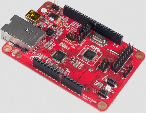
- WIZnet W7500
- 32-bit ARM Cortex-M0
- 128KB Flash / 48 SRAM
- Hardware TCP/IP coe (WIZnet TCP/IP Engine)
- CMSIS-DAP
- SWD Con.
- WIZwiki-W7500 feature
- Arduino Pin compatible
- ISP / SD Slot / REG LED
- Ethernet PHY
Software: TCP recv only
- How to config. Clock
- W7500RM - 10.4.3 PLL frequency calculating register (PLL_FCR)
- Address:0x4100_1014
- Reset value : 0x0005_0200=> 20MHz
These bits are written by S/W to set frequency of PLL output.bits 31-22 21-16 15-14 13-8 7-2 1-0 Desc. RSVD M RSVD N RSVD OD
PLL output frequency FOUT is calculated by the following equations:
FOUT = FIN x M / N x 1 / OD
Where:
M = M[5] x 32 + M[4] x 16 + M[3] x 8 + M[2] x 4 + M[1] x 2 + M[0] x 1 (2 ~ 63)
N = N[5] x 32 + N[4] x 16 + N[3] x 8 + N[2] x 4 + N[1] x 2 + N[0] x 1 (1 ~ 63)
OD = 2 (2 x OD[1]) x 2 (1 x OD[0])
- Psedo-code for PLL_FCR
// main.c
/* External Clock */
CRG_PLL_InputFrequencySelect(CRG_OCLK);
//*(volatile uint32_t *)(0x41001014) = 0x000C0200; // 48MHz
//*(volatile uint32_t *)(0x41001014) = 0x000B0200; // 44MHz
//*(volatile uint32_t *)(0x41001014) = 0x000A0200; // 40MHz
//*(volatile uint32_t *)(0x41001014) = 0x00090200; // 36MHz
//*(volatile uint32_t *)(0x41001014) = 0x00080200; // 32MHz
//*(volatile uint32_t *)(0x41001014) = 0x00070200; // 28MHz
//*(volatile uint32_t *)(0x41001014) = 0x00060200; // 24MHzS
//*(volatile uint32_t *)(0x41001014) = 0x00050200; // 20MHz, Default
//*(volatile uint32_t *)(0x41001014) = 0x00040200; // 16MHz
//*(volatile uint32_t *)(0x41001014) = 0x00030200; // 12MHz
*(volatile uint32_t *)(0x41001014) = 0x00020200; //  8MHz
- W7500RM - 10.4.3 PLL frequency calculating register (PLL_FCR)
- How to config. RX memory buffer
- Iperf test Firmware
- Source Code : https://github.com/embeddist/W7500/tree/W7500_DMA
- W7500/W7500x_Library_Examples/Projects/Peripheral_Examples/WZTOE/IperfTest_DMA/main.c
- TCP only Recv function in iperf.c
int32_t recvonly_tcps(uint8_t sn, uint8_t* buf, uint16_t port)
{
     int32_t ret;
     uint16_t size = 0;
     int32_t i;
     switch(getSn_SR(sn))
     {
        case SOCK_ESTABLISHED :
           if(getSn_IR(sn) & Sn_IR_CON)
           {
              setSn_IR(sn,Sn_IR_CON);
           }
           // Don't need to check SOCKERR_BUSY because it doesn't not occur.
           if((size = getSn_RX_RSR(sn)) > 0)
           {
              if(size > DATA_BUF_SIZE) size = DATA_BUF_SIZE;
              printf("---------------size :%d\r\n", size);
             ret = recv(sn, buf, size);
           }
           break;
        case SOCK_CLOSE_WAIT :
           if( (ret = listen(sn)) != SOCK_OK) return ret;
           break;
        case SOCK_CLOSED:
           if((ret = socket(sn, Sn_MR_TCP, port, Sn_MR_ND)) != sn) return ret;
           break;
        default:
           break;
     }
     return 1;
}
- Sn_RXBUF_SIZE (Socket n RX Buffer Size Register)
Sn_RXBUF_SIZE configures the RX Buffer size of Socket n. Socket n RX Buffer size can be configured with 1,2,4,8, and 16 Kbytes. If a different size is configured, the data cannot be normally received from a peer.Value (dec) 0 1 2 4 8 16 Buffer size 0KB 1KB 2KB 4KB 8KB 16KB - Use wizchip_init() for Setting Sn_RXBUF_SIZE
// main.c /* set Sn_RXBUF_SIZE and Sn_RXBUF_SIZE as 8KB */ uint8_t tx_size[8] = { 8, 0, 0, 0, 0, 0, 0, 0 }; uint8_t rx_size[8] = { 8, 0, 0, 0, 0, 0, 0, 0 }; ... /* Set Network Configuration */ wizchip_init(tx_size, rx_size); - Use API for Setting Sn_RXBUF_SIZE
  uint8 socket_num = 0;
  uint8 rx_buffer_size = 4; // set 4KB
  setSn_RXBUF_SIZE(socket_num, rx_buffer_size);
- Iperf test Firmware
- How to use Direct Memory Access (DMA)
Direct memory access (DMA) is used in order to provide high-speed data transfer between peripherals and memory as well as memory to memory. The DMA controller has up to 6 channels in total, each dedicated to managing memory access requests from one or more peripherals. For more details, refer to “PrimeCell® μDMA Controller (PL230)” from the Technical Reference Manual.
• WZ_TOE-to-memory transfer (software request only)
- Initialization by using API
//main.c /* Init. uDMA */ dma_data_struct_init(); dma_init(); - DMA memory copy in W7500x_dma.c
/* DMA memory copy */ uint32_t chnl_num = 5 ; //DMA Channel number unsigned int src = 0xXXXX_XXXX; // Source Address unsigned int dest = 0xDDDD_DDDD ; // Destination Address unsigned int size = 0; // byte operation unsigned int num = 1024; // data length void dma_memory_copy (chnl_num, src, dest, size, num) - Read/Write DMA functions for WZ_TOE
  //W7500x_wztoe.c
  #define _DEF_ACCESS_DMA_BUF_
  #ifdef _DEF_ACCESS_DMA_BUF_
  #include "W7500x_dma.h"
  #define MAX_TRANSNUM  1024
  void WIZCHIP_READ_DMA (uint32_t BaseAddr, uint16_t ptr, uint8_t* pBuf, uint16_t len)
  {
      /* call void dma_memory_copy () */
  }
  void WIZCHIP_WRITE_DMA(uint32_t BaseAddr, uint16_t ptr, uint8_t* pBuf, uint16_t len)
  {
      /* call void dma_memory_copy () */
  }
  ...
- Initialization by using API
How to use Bandwidth Measurement Tool: Iperf
Iperf is a tool to measure maximum TCP bandwidth, allowing the tuning of various parameters and UDP characteristics. Iperf reports bandwidth, delay jitter, datagram loss.- https://iperf.fr/
# ex.) host IP(192.168.77.9):port[5000], display format is Mbit/sec, interval 1 sec. >iperf.exe -c 192.168.77.9 -p 5000 -f m -i 1- -c : —client host, -c will connect to the host specified.
- -p : —port #, the server port for the server to listen.
- -f : —format [], ‘m’ = Mbit/sec
- -i : —interval #, Sets the interval time in seconds between periodic bandwidth through performance
- Serial terminal for wizwiki_W7500 monitoring
PHY is linked. MAC ADDRESS : 00:08:DC:01:02:03 IP ADDRESS : 192.168.077.009 GW ADDRESS : 192.168.077.001 SN MASK: 255.255.255.000 TEST- START 0:Listen, TCP server loopback, port [5000] 0:Connected - 192.168.77.223 : 1110 // <-- dispaly after TCP_Established from Iperf - Excute Iperp on Command Prompt
Network performances
Analysis of this improvement shows- that the total improvement is due to increasing RX buffer.
- that the total improvement is due to increasing AHB bus Clock.
- that 200% of the total improvement is due to using DMA.
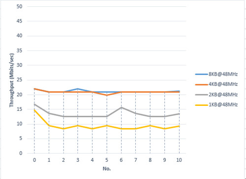
Network performance according to RX Buffer size
- Fig. TOE performance according to RX buffer size ( w/o DMA@48MHz)
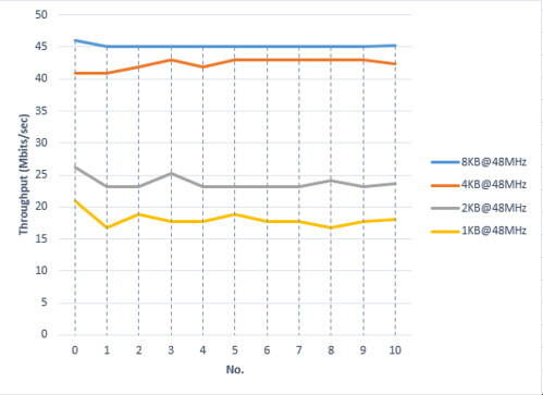
- Fig. TOE performance according to to RX buffer size (w/ DMA@20MHz)
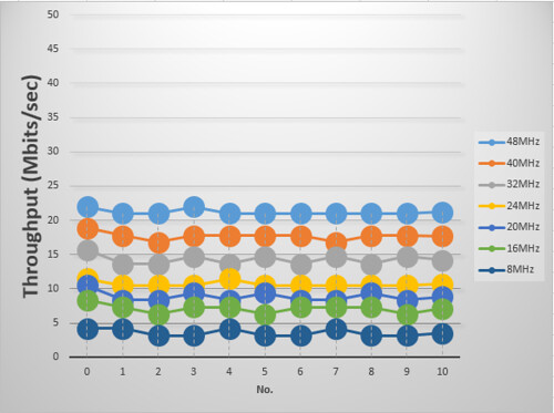
Network performancd according to AHB bus clock
- Fig. TOE performance according to AHB bus clock (w/o DMA, RX Buffer:8KB)
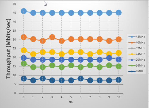
- Fig. TOE performance according to AHB bus clock (w/o DMA, RX Buffer:8KB)
댓글 없음:
댓글 쓰기